Short Example of CFD Simulation of Radial Industrial Fan using OpenFOAM® software
The original motivation for creating this workflow was the requirement of industrial fans designer to have an OpenFOAM® methodology for CFD simulations of their fans. The methodology creation process was pretty similar to the compressor workflow and this methodology later became a part of the Turbomachinery CFD package.
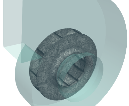
Fan Geometry
The input into this workflow is the fan’s surface geometry usually exported from CAD:
One computational mesh both for transient and steady-state simulations
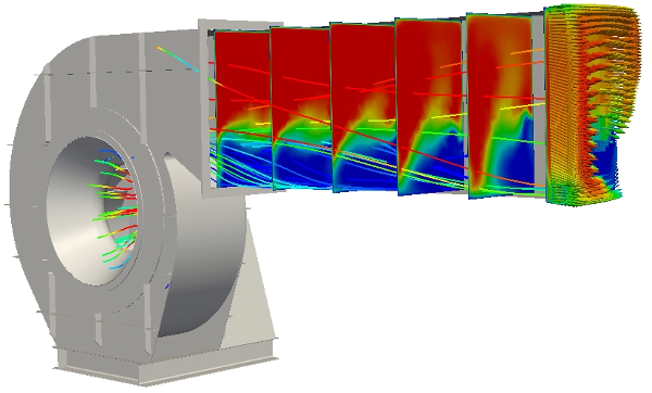
Good idea is to split the computational model into several parts. For example, we can assume three parts: the inlet, the wheel and the outlet part. Each part is constructed individually and meshes can be later merged using mergeMeshes utility. Such a approach allows us using wide range of CFD methods. For mechanical fans we recommend to merge meshes into one big mesh.
The computational mesh is created in OpenFOAM® application snappyhexmesh. Typical input surface formats that can be used are .stl or .obj . The mesh’s interfaces are connected via AMI (Arbitrary Mesh Interface) and having such a mesh, user can later decide to go for steady-state simulation or to go for transient simulation. This approach is called Single-region. Another option is to use Multi-region approach. The multiregion solver switches between regions (meshes) and computes them individually. There can be employed even more CFD techniques like Mixing-plane averaging, periodic boundary conditions for symmetric parts, etc …
Transient solver vs. Steady-state solver
There is a big decision to be made. To run transient or steady-state simulation. Transient simulation give slightly better results, but takes ages to meet at least several wheel rounds. Steady-state simulation is quick, but may not be as accurate as transient simulation. As a results, steady state simulations are used more for rapid prototyping and later selected design candidates are also run as transient.
For steady-state simulation one can use solver based on rhoSimpleFoam . For transient simulation one can use solver based on rhoPimpleDyMFoam . We also recommend to tune the standard OpenFOAM® solvers a little bit. Very useful may be to employ limits on selected quantities, or writing down a minimum and maximum of all quantities during the simulation, and many more …
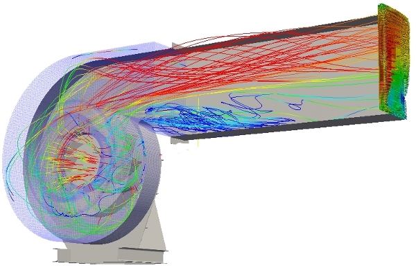
The fan cfd workflow covers complete process from basic (usually CAD) data over the CFD analysis to significant engineering results. It is completely automated to save reasonable amount of time and resources.
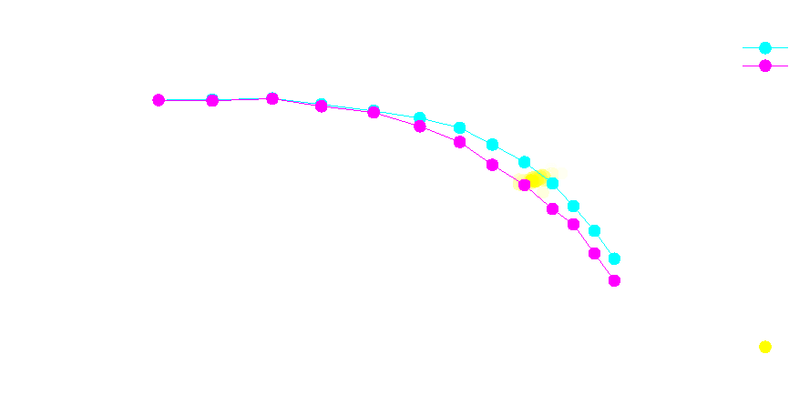
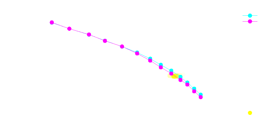
Before the beginning of the simulation the working points are specified in the configuration file in terms of static pressure or nondimensional loss coefficient. The script can run the simulation on each of those working points until the whole fan characteristic is computed. When the simulation is finished the results may be automatically evaluated and graphs are automatically plotted plotted in Gnuplot.
Many people think the biggest benefit of OpenFOAM® is it is free of charge. But experiences show the biggest benefit of using OpenFOAM® is its focus and customizability.
This offering is not approved or endorsed by OpenCFD Limited, producer and distributor of the OpenFOAM software and owner of the OPENFOAM® and OpenCFD® trade marks.
Stay Informed about news in CFD and our company. We do not like Spam. You can unsubscribe anytime.