CFD SUPPORT introduces the new generation of CFD simulations. TCFD brings an extreme increase of productivity to CFD simulations. TCFD is extremely popular project, because it successfully merged benefits of an open-source (perpetual, unlimited users, jobs, and cores, customizable, …) with benefits of commercial codes (professional support, well tested, ready for the industry, robust, accurate, automated, GUI, …).
TCFD is fully automated, it can run the whole workflow by a single command: data input, new case is written down, mesh is created, case is set-up, case is simulated, results are evaluated and the results report is written down. Both GUI and batch mode. Data in – data out. TCFD is mainly focused on supporting the engineers in their real value added work. TCFD is fully automated and the beauty of TCFD is that it is the user who decides how deep to dive into a CFD or not at all. And all the options remain open at the same time.
The input data
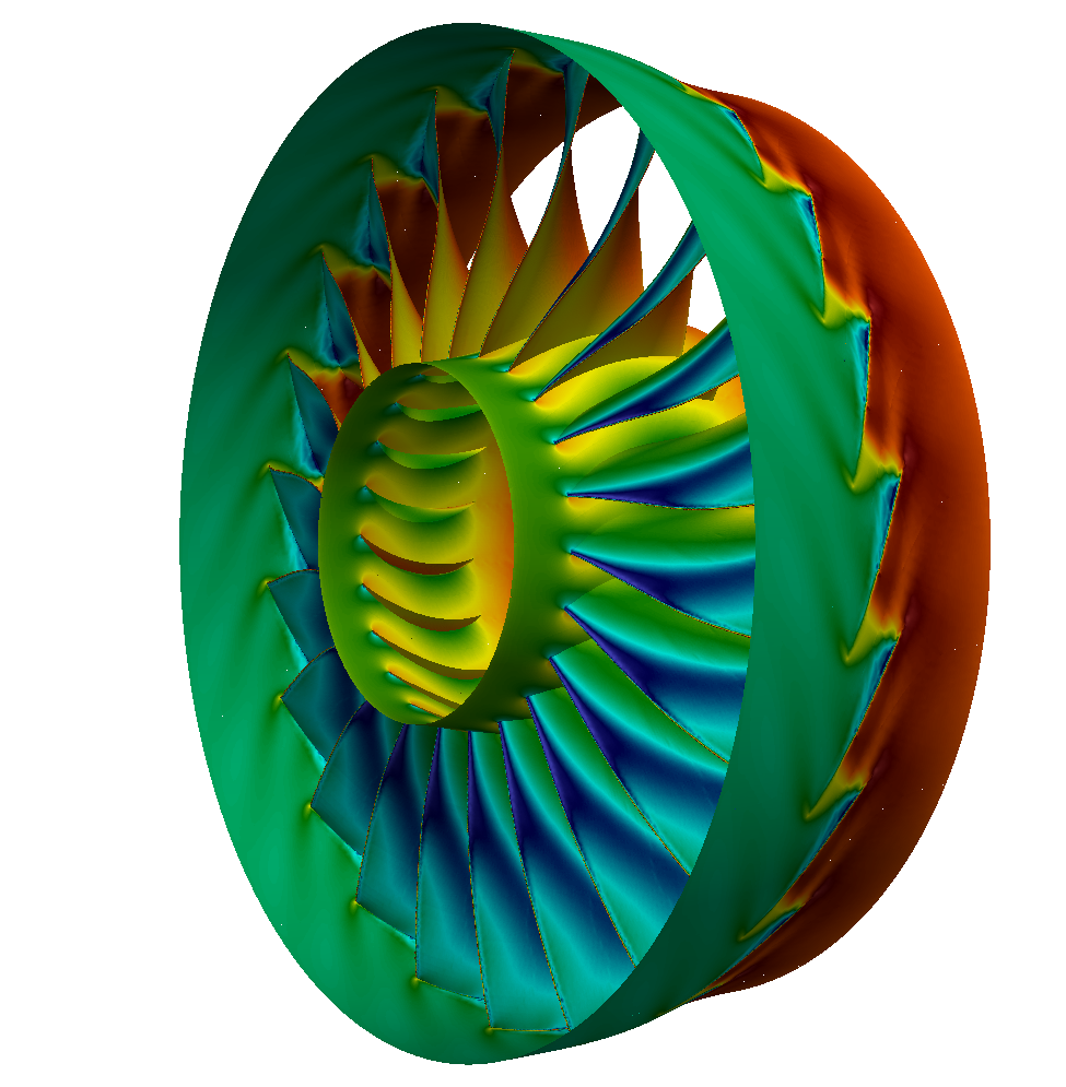
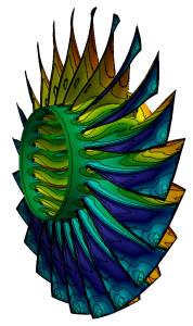
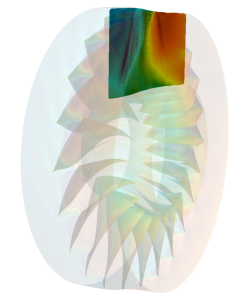
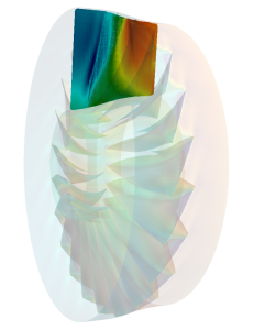
The NASA Rotor 67 axial compressor was simulated. The measurement data is available for results comparison. Rotor has 22 blades – periodic segment of single one blade region is computed. The surface model data in .stl file format together with physical inputs are loaded in TCFD. Other option would be loading an external mesh in OpenFOAM® mesh format, or loading an MSH mesh format (Fluent mesh format). This CFD methodology employs a multi component approach, which means the model is split into a certain number of regions. In TCFD each region can have its own mesh and individual meshes comunicate via interfaces.
Easy to test the mesh sensitivity
In practise the rough mesh with no boundary layer (CPU time: 4 core*hours/single point) can give the same results as the fine mesh with boundary layer (CPU time: 20 core*hour/point). So finally, the rough mesh effect can eliminate the lack of boudary layer. Anyway, with fully automated workflow it is easy to make many tests to callibrate to actual machine.
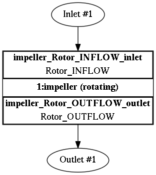
The component graph
Any project simulated in TCFD has its component graph. The component graph shows how the components are organized – the model topology. What is the inlet, the outlet and how the components are connected via interfaces.
CFD Simulation Set-up
Compressible flow model
Steady-state flow model
Medium: Air
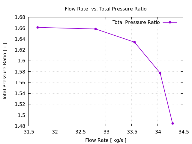
BEP Pressure ratio: ΔpTot = 1.66 [-]
Temperature at inlet: T = 25 [ºC]
Viscosity: μ = 1.831e-5 [Pa.s]
Rotation speed: 16043 [RPM]
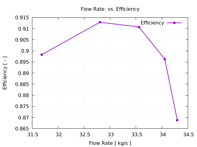
BEP Mass Flow Rate: 33 [kg/s]
Interface: None
Turbulence Model: k-ω SST
Mesh: snappyHexMesh, hexadominant
Mesh Cells: 463938
Mesh Average y+ (full/segment): 112 [-]
CPU time (per point): 24 [core.hours]
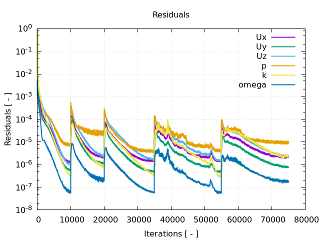
Running CFD Simulation
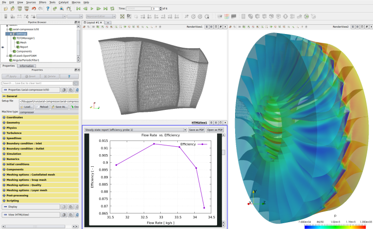
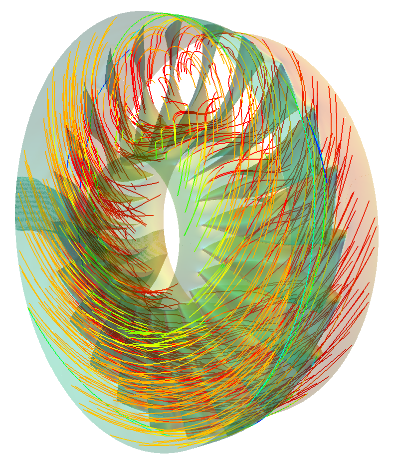
The simulation can be run on any number of parallel processors. Immediately after the simulation is started, the user can follow the progress of all the important quantities in a HTML report: flow rates, residuals, efficiency, torque, pressure difference and many others. These run-time functions give the user valuable information of the simulation convergence and also the availability to stop the simulation before its expected end.
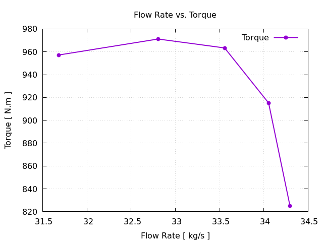
The workflow computes complete characteristics point by point.
The simulation results are examined in ParaView. ParaView is CFD postprocessing tool providing all standard features for analyzing CFD data.
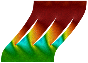
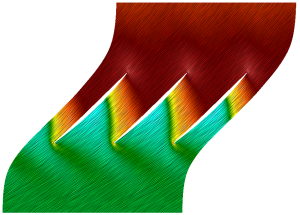
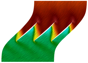
CFD Support developed a special extension to ParaView for visual postprocessing rotating machinery: Turbo Blade Post, which is special set of filters for ParaView to enable for example blade-to-blade view, or meridional average.
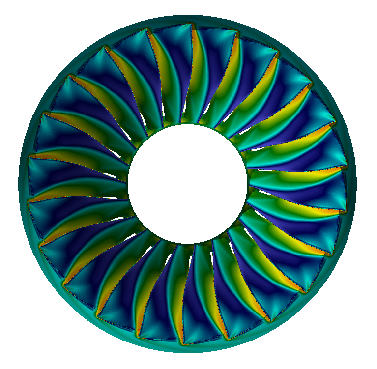
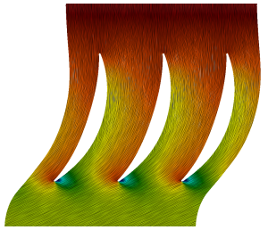
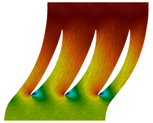
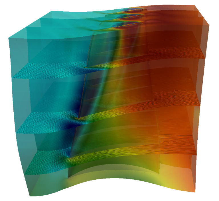
Blade to blade view. Within the Turbo Blade Post, the impeller mesh can be unwrapped to be able to slice it. The computed quantities are displayed at a certain radial coordinate – anywhere along with the blade height. With such an unwrapped mesh it is also possible to plot all the quantities along the blade height and also plot quantities around the blade surface, etc.
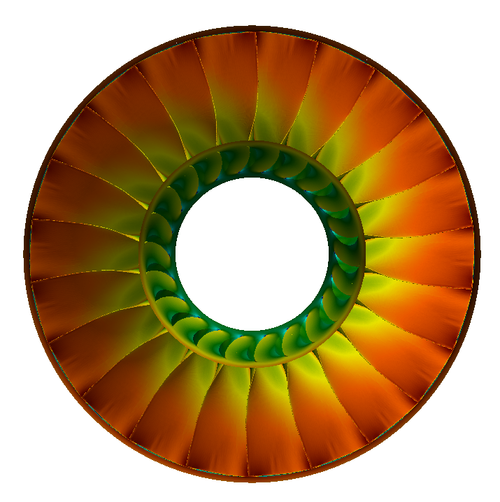
Another Turbo Blade Post function is the Meridional Average which creates a meridional plane of circumferential averages of all simulated quantities.